Tuesday, January 20, 2009

Design Images

I thought I'd post some images of what the house is intended to be, when it's all said and done.  I've been using Autocad to draft up plans, sections and elevations of the design.  Autocad is practically the industry standard for architects and some engineers to draft drawings of various sorts in the computer.  It's sort of like drafting things by hand except faster.  The images below, however, were done in a 3D modeling program called Sketchup.  It is a very simple program, also free from google.  It's super-easy to use and a convenient way to visualize spaces and objects in three dimensions.  Therefore, its a good tool to understand the spaces prior to building them to make sure everything works out.  This particular program isn't the best tool for photo-realistic renderings, but it works for simple exercises like this.

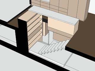
Below are two images, one from a birds-eye view and another at eye level.  The street and front entry are at the second floor to the left.  The backyard is to the right.  You enter the house from an exterior staircase leading to the second floor.

As you enter, you find yourself in the living room.  To your right is the third bedroom which will most likely be used as an office.  The staircase and kitchen are integrated, and are located behind the living room.  The 'island' kitchen counter, shown in dark brown, will contain the sink and will serve as the guardrail so you don't fall to the floor below.  To the top of the drawing is the bathroom flanked on each side by bedrooms.

A tall wall of cabinetry, shown in tan,  separates bedroom 2 from the kitchen. Starting from the top right, this cabinetry forms the closet for bedroom 3, a coat closet facing the living room, tall kitchen items (refrigerator, pantry, oven, appliance garage), and a counter for the stove.  In addition to being a room divider, this cabinetry will also hide ductwork at it's base, supplying the heat to all rooms of the house.  It also contains the energy efficient up-lights at the top, which will shine onto the high ceiling above.  The lights will be hidden from one's view.  Since the fluorescent lights will reflect from the ceiling, the harshness typically associated with fluorescents will be reduced.  Therefore the tan 'L' functions as a divider of space, storage for a variety of functions, and a conduit for electrical and heating utilities.  It's called 'poche', 'diagram', or 'parti' in archi-speak.

As the cabinet wall will stop well short of the ceiling, the only wall in the middle of the house that extends from floor to ceiling is between 'bath 1' and 'bdrm 2'.  This wall provides structural, lateral support and holds the plumbing utilities.  Every other wall stops at an 8' high datum.  This will provide greater natural light to all spaces and will allow you to perceive the high cathedral ceiling from all rooms in the house.  Since the home is small and square footage is not very generous, a high ceiling and open plan will help to make the house feel larger and more comfortable.

The kitchen counter, shown in dark brown, stops and then starts again in the dining room.  The dining room is located in the existing sunroom addition.  This will be right next to the deck.  I hope to eventually put a large sliding door between the deck and dining room, allowing the eating area to open to the outside on a warm day.  The ceiling over the dining room is lower than the rest of the house.  I'm thinking to paint this entire volume a fun, bright color, giving a counterpoint to the white walls and ceiling.

The staircase leads you down toward a bookshelf and then under the kitchen counter.  Usually, there are cabinets under counters, but to allow headroom without sacrificing valuable space, we're going to omit the cabinets, allowing headroom as you descend the stairs.  The stair landing is about 2'-6" above the ground floor level, the ideal desk height.  This landing forms a 'plinth' and will extend to the right, beyond the stair, forming a desk at the office area.

To the right of the office will be the family room.  Because of the exterior stair, this area has little natural light.  The open stair and skylights at the roof above will help bring light to the dark ground floor level, but this area will be ideal for an entertainment center and tv.

To the left of the stairway, under the dining room, will be the master bedroom.  Eventually, similar to upstairs, I'd like to add a large sliding door.  On nice days, the master bedroom will have direct access to the backyard and garden. (as if we have any idea how to garden)

Not shown is the garage and master bathroom on the ground floor.  The garage basically stays in the same place, and will house the water heater, a laundry area, furnace, and electrical panel as well as one car.  Behind the garage, and next to the office, will be the master bathroom.

All in all, we'll have about 1500 habitable square feet, 3 bedrooms, and 2 bathrooms.  We're trying to make the most out of a small space.  Hopefully, every square inch will be utilized efficiently and simply.  In addition, the design will try to take advantage of an open floor-plan, high ceilings, and visual connection between the two floors.  This should give a generous and open feeling to a space that could easily feel cramped.  With a tight budget, locating plumbing and heating systems in a straightforward and simple manner will help to keep costs down.

Here are those images:


Those are my thoughts so far.  Any feedback or suggestions would be appreciated, preferably before I start to build walls!

Monday, January 12, 2009

Raise the roof (sorta)

Last week, I raised our house off the ground all by myself.

More accurately, I raised a portion of the house about 1/2", but nevertheless, part of the house is now higher than it once was.  Here's how:

Soon after demolition was finished, we found the middle wall on the ground floor to be a bit wimpier than it should be.  This wall supports half of the entire floor above, and is quite important.  It sat on a very thin bit of concrete, instead of a proper footing with rebar.  Instead of re-doing the entire wall and foundation, we decided to put in beefier posts at 6' intervals to hold up the floor above.

First, we had to jackhammer the existing deficient concrete, and dig a hole 2 feet square and 18 inches deep.  There were 3 such holes.  Here is a picture of one of them:


After putting in metal reinforcing bar into the hole, we mixed and poured concrete.  The concrete was smoothed out to be flush with the rest of the floor, and a metal post base was partially embedded into the wet concrete.


Next, the hard part.  I took my trusty laser level, and shot a perfectly horizontal line across the bottom of the beam these posts were to support.  I found the beam to be quite wavy, with a significant dip of about 1/2" in the center.  One end of the beam was also lower than the other.  I realized that I couldn't raise either end of the beam, but I it did seem possible to raise the middle.  Making possibilities reality is not so easy. With a sledgehammer, extra 2x4's, leverage, and the laws of physics, I raised our house.

I first measured the space between the ground and the beam.  Then I cut some wood to be slightly taller than that space.  I wedged the wood between the ground and beam at an angle, and sledgehammered it until it was vertical.  You can see it buckling slightly under the weight of the floor above here:


This was done twice for every post.  One temporary piece was wedged to the left and another to the right of the new post location.  But cutting these temporary pieces taller than the space, I slowly raised the beam back to horizontal.


Next I repeated the process with the actual permanent 4x4 post.  It sits at the bottom in the 'post base' that was previously cast into the concrete.  A 'post cap' at the top connects it to the existing beam.


Many hours and much noisy sledgehammering later, the post is finally installed in it's correct location, and the beam is level:


I knocked out the two temporary pieces.  Here are two posts installed.  I still have one more in the middle to complete.


When finished, the new concrete footings and posts will have sufficient bearing capacity to hold the furniture, walls, roof, and people on the floor above.  The beam should stay level and the concrete should not settle.

Stairs! Part II

So as Denise wrote previously, we have been framing a new hole in the second floor.  This hole will eventually contain a staircase, connecting the ground floor with the second.  The problem with cutting a hole in your floor is that you end up with unsupported floor joists.  There are pieces of wood within the floor, running in a linear fashion, that need to be cut through.  Bigger pieces of wood need to support these pieces to be cut.  Gravity loads (you're fat self walking around for example) need to be transfered to the ground through from yourslf through the subfloor, then floor joists, then beams, then walls or columns, and finally the foundation.  Our stair hole is just about done; here are some more pictures of the progress.

Here is a simple image of the stair configuration we hope to achieve.  You will walk down the stairs along the exterior wall and then turn right.  You actually end up walking under the kitchen counter, allowing us to save some valuable square footage.  The landing will extend under the rest of the stair, at the correct height for a desk or other work area.


Continuing the images that Denise posted the other day, here is the hole.  The subfloor was cut out with a circular saw, none of those support pieces of wood have been put in yet.


This past Saturday, we put in the necessary beams and columns to frame out the hole, allowing the floor joists to be cut.  There is one large beam at the top of the 'L', 6x10 PSL.  3 additional medium size pieces, 4x8s frame out
 the rest of the hole.  A wood column is in the corner.  It's temporary, as I'd like to replace it with a more slender steel piece in the future.  This is the almost finished hole.

Thursday, January 8, 2009

Stairs!

Lots has been happening over at our house over the last couple weeks. Unfortunately, Ryan has been downloading most of the pictures we've taken at work, which makes it difficult for me to post them on the blog. Briefly, here are some of the highlights of what's been going on:

- Our crew of construction guys has been working on putting in additional framing on our roof. This is necessary since we took out the old truss system that had previously been holding the roof up. We have lots of pictures of this, but, as I said, they are at Ryan's work.

- We've had new plumbing installed in the garage in what will eventually be the master bath. We passed inspection on that, so yay us!

And then finally, we cut the hole in the floor where we will be building an interior staircase (currently, the only way to get from upstairs to downstairs requires one to go outside).
So these are some pictures of what will hopefully soon be a staircase:

The red tape is outer boundary of our hole. It took us nearly 3.5 hours to measure out that hole. In the process of measuring, we discovered that our walls are not straight. Very fun.
Ryan, in action, ripping up the sub-floor.

It was a pretty cold, dark night that we did this

Our hole.

This picture was taken looking up from underneath the hole. You can see a little bit of the new lumber holding up the roof.